Modeling Guide for 3D Objects - Part 2: Modeling of Buildings (LoD1, LoD2, LoD3)
Document History
|
Version |
Date |
Author(s) |
Status |
Remarks |
|
2.0.0 |
März 2013 |
SIG 3D / AG Qualität © 2013 Special Interest Group 3D (SIG3D) der GDI-DE http://www.sig3d.org |
öffentlich |
Erste öffentliche Version mit Erweiterter Modellierung; |
|
2.0.0 EN |
November 2013 |
SIG 3D / Quality Working Group © 2013-2014 Special Interest Group 3D (SIG3D) of the Spatial Data Infrastructure Germany (GDI-DE) http://www.sig3d.org /EC, KHH |
public |
English version; |
|
2.0.1 EN |
November 2017 |
SIG 3D / Quality Working Group EC, KHH |
public |
License changed to Creative Commons BY-NC-SA 4.0; |
Introduction
Scope
- The modeling recommendations are usually independent from the recording method. That means that this document is not a recording manual.
- This document describes the modeling of 3D objects on the basis of existing information. In case of lacking information, in particular in case of missing height information, objects must explicitly not be modeled. For example, if all relevant information on balconies is available, this document provides recommendations for a standardized modeling. Otherwise balconies must not be modeled.
- Recommendations are related to the Open Geospatial Consortium (OGC) standard CityGML version 1.0 and 2.0.
- This document refers to national (German) and European standards (AdV, INSPIRE) and can only be partially generalized.
- This document is restricted to the outer shell of buildings, i.e. building modeling up to LoD3
Target Group
- Modeler
- Data holder
- Developer
Prior Knowledge Required
- GML: Geography Markup Language
- CityGML: Application schema for GML for the representation, storage, and exchange of virtual 3D city and landscape models
- ALKIS: Official German Land Registry Information System
Further References
Document Conventions
- Features are written in italic characters with the corresponding name space in bold characters .
- Examples are written in fixed width.
- Online references to other internal or external pages and documents are written in blue.
- A statement which is not valid for all Levels of Detail (LoD) is noted as (LoD[1234][+]), e.g. a notation with (LoD1) is only valid for LoD1, a notation (LoD2+) is valid for all LoDs from LoD2 and above.
Definitions und Determinations
Level of Detail (Building, BuildingPart)
Definitions of SIG 3D:
- LoD0
- For every building or building part the footprint or roof outline is represented by a horizontal polygon with a well defined absolute and constant height.
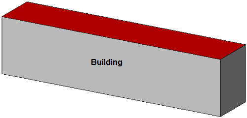
- LoD1
- For every building or building part the generalized outer shell is represented by exactly one prismatic extrusion solid. Ground, floor and roof surfaces must be horizontal, lateral boundary surfaces must be vertical.
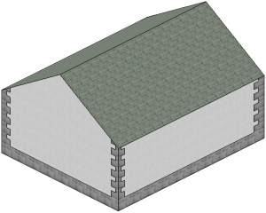
- LoD2
- For every building or building part the geometrically simplified outer shell is represented by horizontal resp. vertical outer surfaces and simplified roof shapes. All kind of surfaces ( e.g. ground surfaces, wall surfaces, roof surfaces, outer ceiling surfaces, outer floor surfaces, virtual closure surfaces ) and additional building elements ( e.g. building installations like balkonies, dormers and chimneys ) may be represented as semantic objects.
- LoD3
- For every building or building part the geometrically detailed outer shell is represented by detailed outer surfaces and detailed roof shapes. All kind of surfaces ( e.g. ground surfaces, wall surfaces, roof surfaces, outer ceiling surfaces, outer floor surfaces, virtual closure surfaces ) and additional building elements ( e.g. building installations like balkonies, dormers and chimneys ) may be more detailly represented as semantic objects. In respect to LoD2 doors and windows can be modeled as planar thematic objects.
- LoD4
- For every building or building part the geometrically detailed outer shell and interior is represented by detailed outer and inner surfaces and detailed roof shapes. All kind of surfaces ( e.g. ground surfaces, inner and outer wall surfaces, inner and outer roof surfaces, outer ceiling surfaces, outer floor surfaces, virtual closure surfaces ) and additional movable and non movable building elements ( e.g. building installations like balconies, dormers, chimneys, interior and furniture ) may be represented with greater detail as semantic objects.
Reference Coordinate System
CityGML 2.0 strongly recommends the specification of a reference coordinate system. For a meaningful use of data a valid reference coordinate system is imperative, therefore a valid reference coordinate system must be defined for each instance file:
- A reference coordinate system must be defined as three dimensional (usually position and height reference system --> see Compound Coordinate Reference System).
- A reference coordinate system should not be changed within an instance file.
- A reference coordinate system should be defined once within <gml:Envelope>.
Recommendations for Germany: ETRS89 / UTM / Reference ellipsoid GRS80 + DHHN92
CityGML Example:
<gml:boundedBy>
  <gml:Envelope srsDimension="3" srsName="urn:adv:crs:ETRS89_UTM32*DE_DHHN92_NH">
  --> see Compound Coordinate Reference System
     <gml:lowerCorner srsDimension="3">458868.0 5438343.0 112.0 </gml:lowerCorner>
     <gml:upperCorner srsDimension="3">458892.0 5438362.0 117.0 </gml:upperCorner>
  </gml:Envelope>
</gml:boundedBy>
ALKIS Example:
<gml:boundedBy>
   <gml:Envelope srsName="urn:adv:crs:ETRS89_UTM32">
      <gml:pos>367456.554 5718128.391</gml:pos>
      <gml:pos>367505.094 5718091.143</gml:pos>
   </gml:Envelope>
</gml:boundedBy>
see also Modeling Guide for 3D Objects - Part 1
Model Structure
The use of core:CityModel is not regulated explicitly in the specification and in the schema. The multiple use of core:CityModel is compliant to the schema and will be validated. In order to avoid conflicts while importing CityGML models, it is recommended to use exactly one instance of core:CityModel as root element.
Heights
The measuredHeight is the measured or computed difference between the lowest terrain intersection point and the highest roof point with the following properties:
- the measuredHeight is a simple attribute and so can not be specified and/or qualified any further;
- the measuredHeight is always related to the real building;
- the measuredHeight is independent of the LoD of the building;
- the computation of the measuredHeight should always base on the terrain model with the highest available resolution.
The following heights are valid for flat roofs, outshot roofs, gable roofs, hip roofs, jerkinhead roofs, mansard roofs, pyramid roof, shed roof, shells and domes:

The following heights are valid for all kind of shed roofs:

The following heights are valid for different roof overhangs:

If absolute heights for the noted values are needed, they have to be defined as generic attributes (dimensioned gen:measureAttribute):
- <gen:measureAttribute name="min height surface"><gen:value uom="#m">Value</gen:value></gen:measureAttribute>
- <gen:measureAttribute name="min height eaves"><gen:value uom="#m">Value</gen:value></gen:measureAttribute>
- <gen:measureAttribute name="max height eaves"><gen:value uom="#m">Value</gen:value></gen:measureAttribute>
- <gen:measureAttribute name="max height ridge"><gen:value uom="#m">Value</gen:value></gen:measureAttribute>
Terrain Intersection Line
In CityGML the terrain intersection line is an attribute of a building or building part. It is generated by intersection of the building or building part with the terrain and has the following properties:
- a terrain intersection line can be measured or calculated ;
- if a terrain intersection line is calculated, the terrain model with the highest resolution available should be used;
- a terrain intersection line is an attribute of the building or building part;
- outer building installations (bldg:BuildingInstallation) are taken into account from a terrain intersection line (see Figure A);
- a terrain intersection line is a result of the intersection of buildings in the respective LoD and the most accurate available terrain. In CityGML it has no relation to the terrain used in a visualization and its resolution and accuracy.
- a terrain intersection line may consist of several independent parts;
- a terrain intersection line need not be closed;
- a terrain intersection line which does not exist in reality will not be taken into account (e.g. in the case of building parts ).
|
|
|
|
|
|
Figure A |
Figure B |
Figure C |
Figure D |


Overhanging Building Elements
Overhanging or projecting building elements are defined as parts of roofs, walls etc, which should not be considered in the volume calculation of the building. Overhanging or projecting building elements are modeled as follows:
- always as from the volume-forming building element separated surface element(s) (see Figure A)
- always as a surface element, if the thickness of the building element is less than 0.5 m (see Figure B)
- always as a solid element, if the thickness of the building element is greater than 0.5 m (see Figure B)
- in LoD2 always as a surface element, if the thickness of the building element is less than 0.5 m
- in LoD2 always as a solid element, if the thickness of the building element is greater than 0.5 m
- in LoD3 always in the best accuracy based on available information.
|
|
|
Figure A |

|
|
|
Figure B |

Closed Coverage Type
Buildings as parts of closed coverage type (applies to semi-detached and terrace houses also) can be modeled as follows:
- Buildings that are separated within the land register should be modeled as separate buildings.
 |  |
| Separate buildings of closed coverage type | Terrace houses as separate buildings |
- Buildings that are united within the land register should be modeled as one single building which can be subdivided into building parts (e.g. row of buildings, semi-detached or terrace houses).
 |  |
| Terrace houses as one single building | Terrace houses as building parts |
- Buildings without any land register information and for which the building detection provides no usable structures (e.g. based on flights) should be modeled as one single building.
Terrace houses as one single building
The modeling of boundary surfaces between buildings must satisfy the following geometric resp. semantic conditions:
- Common boundary surfaces may only be referenced within a building via Xlink (building-building part resp. building part - building part).
Addresses
- The CityGML specification allows to assign an address both to a building (bldg:Building, bldg:BuildingPart) as well as to a door (bldg:Door). It is recommended always to assign an address to a building (in any LoD) because doors are not available in LoD1 and LoD2.
- It is recommended to use the complete postal address.
- Multiple addresses can be assigned to one building.
- Umlauts are allowed in addresses (z.B. Würzburg☺, Wuerzburg☺, Würzburg and Wuerzburg mixed ☹).
General example:
Street:            Hermann-von-Helmholtz-Platz
Number:            1
Zip Code:          76344
City:              Eggenstein-Leopoldshafen
CityGML example:
<core:Address>
   <core:xalAddress>
      <xAL:AddressDetails>
         <xAL:Locality Type="Town">
            <xAL:LocalityName>Eggenstein-Leopoldshafen</xAL:LocalityName>
            <xAL:Thoroughfare Type="Street">
               <xAL:ThoroughfareNumber>1</xAL:ThoroughfareNumber>
               <xAL:ThoroughfareName>Hermann-von-Helmholtz-Platz</xAL:ThoroughfareName>
            </xAL:Thoroughfare>
            <xAL:PostalCode>
               <xAL:PostalCodeNumber>76344</xAL:PostalCodeNumber>
            </xAL:PostalCode>
         </xAL:Locality>
      </xAL:AddressDetails>
   </core:xalAddress>
</core:Address>
Codelists
Codelists for the CityGML 2.0 standard are available at "http://www.sig3d.org/codelists/standard".
The recommendations for codelists in this modeling guide refer to the proposal of the SIG3D. These codelists are availabe (in German only) at "http://www.sig3d.org/codelists/Handbuch-SIG3D" and relate to ALKIS.
This modeling guide refers to the following codelists:
- Building resp. building part (bldg:Building / bldg:BuildingPart)
- class http://www.sig3d.org/codelists/Handbuch-SIG3D/building/2.0/CL-V1.0/_AbstractBuilding_class.xml
- function http://www.sig3d.org/codelists/Handbuch-SIG3D/building/2.0/CL-V1.0/_AbstractBuilding_function.xml
- usage http://www.sig3d.org/codelists/Handbuch-SIG3D/building/2.0/CL-V1.0/_AbstractBuilding_usage.xml
- roofType http://www.sig3d.org/codelists/Handbuch-SIG3D/building/2.0/CL-V1.0/_AbstractBuilding_roofType.xml
- Building installations (bldg:BuildingInstallation)
Generic Attributes
Generic (user defined) attributes may be used to represent attributes which are not covered explicitly by the CityGML schema. Generic attributes must be used with care; they shall only be used if there is no appropriate attribute available in the overall CityGML schema. Otherwise, problems concerning semantic interoperability may arise. Interoperability of generic attributes is reduced to attribute values which can only be interpreted semantically by additional information. The following attribute types are defined:
- stringAttribute - for arbitrary strings
- intAttribute - for dimensionless integer numbers
- doubleAttribute - for dimensionless floating point numbers
- dateAttribute - for dates with integer-valued year, month and day representation in the format YYYY-MM-DD (e.g. 2013-03-08)
- uriAttribute - represents a Uniform Resource Identifier Reference (URI) (e.g. a link to a document or a web site)
- measureAttribute - for dimensioned values (CityGML 2.0)
Attributes can be combined in CityGML 2.0 by generic attribute sets genericAttributeSet with an optional codeSpace. If the codeSpace attribute is present, then its value should identify an authority for the set, such as the organisation or community who defined its content. The generic attribute set may contain arbitrary generic attributes.
CityGML Examples
<gen:stringAttribute name="construction"><gen:value>concrete</gen:value></gen:stringAttribute>
<gen:intAttribute name="entries"><gen:value>3</gen:value></gen:intAttribute>
<gen:doubleAttribute name="floor area ratio FAR"><gen:value>0.33</gen:value></gen:doubleAttribute>
<gen:dateAttribute name="approval date"><gen:value>2012-03-09</gen:value></gen:dateAttribute>
<gen:uriAttribute name="website "><gen:value>http://www.sig3d.org</gen:value></gen:uriAttribute>
<gen:measureAttribute name="building width"><gen:value uom="#m">10.00</gen:value>/gen:measureAttribute>
<gen:genericAttributeSet name="Base Quantities">
   <gen:measureAttribute name="Height"><gen:value uom="#m">9.00</gen:value></gen:measureAttribute>
   <gen:measureAttribute name="Area"><gen:value uom="#m2">80.00</gen:value></gen:measureAttribute>
   <gen:measureAttribute name="Volume"><gen:value uom="#m3">720.00</gen:value></gen:measureAttribute>
</gen:genericAttributeSet>
Geometry
There is no GML Profile for CityGML. This means that CityGML instance files will validate with every GML geometry. The specification restricts the usage of GML geometry classes (CityGML 2.0 Annex D "Overview of employed GML3 geometry classes). CityGML references to the following geometry classes (CityGML 2.0 Annex D):
|
Abstract Classes |
Instantiated Classes |
Further Limitations |
|
gml:_Solid |
gml:Solid |
only gml:OrientableSurface, gml:Polygon, gml:CompositeSurface, tex:TexturedSurface (obsolete) |
|
gml:CompositeSolid |
no restriction | |
|
gml:_Surface |
gml:Polygon |
only gml:LinearRing and gml:Ring exclusively with gml:LineString or gml:CompositeCurve |
|
gml:OrientableSurface |
no restriction | |
|
tex:TextureSurface |
obsolete | |
|
gml:CompositeSurface |
only gml:OrientableSurface, gml:Polygon, gml:CompositeSurface tex:TexturedSurface (obsolete) | |
|
gml:TriangulatedSurface |
no restriction | |
|
gml:Tin |
no restriction | |
|
gml:_Curve |
gml:LineString |
no restriction |
|
gml:CompositeCurve |
gml:LineString and gml:CompositeCurve only | |
|
gml:_GeometricPrimitive |
gml:Point |
no restriction |
|
gml:_Coverage |
gml:RectifiedGridCoverage |
no restriction |
|
gml:_AbstractGeometricAggregate |
gml:MultiSolid |
no restriction |
|
gml:MultiSurface |
only gml:OrientableSurface, gml:Polygon, gml:CompositeSurface, tex:TexturedSurface (obsolete) | |
|
gml:MultiCurve |
only gml:LineString and gml:CompositeCurve | |
|
gml:MultiPoint |
no restriction | |
|
gml:GeometricComplex |
restricted to connected linear networks | |
|
gml:MultiGeometry |
restrictrions see allowed geometry types |
In order to keep the instance files small and to ensure an optimal editability of models, maximum flat polygons should be used, if appropriate with holes (inner rings).
File Name
It is recommended to use *.gml as file extension to distinguish CityGML files from other XML files.
Modeling
Base Modeling
The base modeling includes the modeling of the building resp. building part itself in LoD1, with appropriate boundary surfaces in LoD2 and LoD3 and with windows and doors in LoD3. In addition, the basic modeling covers the general use of building installations.
Building (bldg:Building)
Definition
SIG3D: A free-standing self-supporting construction that is roofed, usually walled, and can be entered by humans and is normally designed to stand permanently in one place. It is intended for human occupancy (for example: a place of work or recreation), habitation and/or shelter of humans, animals or things.
ISO: Provision of shelter for its occupants or contents as one of its main purposes; usually partially or totally enclosed and designed to stand permanently in one place
CityGML Feature
bldg:Building
Geometry
gml:Solid see Modeling Guide - Part 1
It is recommended to use gml:Solid depending on the LoD in the following way :
- In LoD1 a solid directly contains the bounding geometry (Figure A)
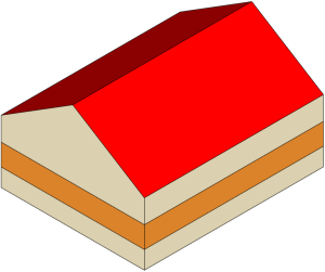
- In LoD2 and LoD3 a solid contains external references (Xlinks) to the bounding geometry (wall surfaces, roof surfaces, ground surfaces, outer ceiling surfaces, outer bottom surfaces and closure surfaces as well as doors and windows) (Figure B) ( see also conformance requirement no. 4 in chapter 10.3.9 of the CityGML V2.0 specification )
|
|
|
|
Figure A |
Figure B |


gml:MultiSurface (not recommended)
gml:MultiCurve (not recommended)
Attributes
- gml:id (mandatory)
- from GML version 3.2 onwards an id is mandatory
- gml:name (recommended, if available in the underlying land register)
- 'name' is the proper name or the name of the building.
- bldg:class (LoD1, LoD2, LoD3)
- The attribute bldg:class allows an unspecified classification of the building; no suggestion from the SIG3D;
- bldg:function (LoD1, LoD2, LoD3) (recommended)
- The 'function' of a building is the predominantly functional significance of the building at the date of data collection ( principle of dominance ); see also in the SIG3D code lists.
- bldg:usage (LoD1, LoD2, LoD3) (conditionally recommended)
- The 'usage' of a building describes the use of the building and contains the respective percentage usage share of the total use.
- bldg:yearOfConstruction (LoD1, LoD2, LoD3) (recommended)
- The 'yearOfConstruction' is the year of completion of the construction or alteration of the building;
- bldg:yearOfDemolition (LoD1, LoD2, LoD3)
- The 'yearOfDemolition' is the year of deconstruction of the building;
- bldg:roofType (LoD1, LoD2, LoD3) (recommended)
- 'Roof type' describes the characteristic shape of the roof; see also in the code list of the SIG3D
- bldg:measuredHeight (LoD1, LoD2, LoD3) (recommended)
- 'Measured height' is the difference in [m] between the highest point of the roof structure and the defined footprint of the building; see also Heights
- bldg:storeysAboveGround (LoD1, LoD2, LoD3) (recommended, if available in the underlying land register)
- 'storeys above ground' is the number of above-ground floors
- bldg:storeysBelowGround (LoD1, LoD2, LoD3) (recommended, if available in the underlying land register)
- 'storeys below ground' is the number of underground floors
- bldg:storeysHeightsAboveGround (LoD1, LoD2, LoD3)
- Height between two consecutive floors of the above-ground floors
- bldg:storeysHeightsBelowGround (LoD1, LoD2, LoD3)
- Height between two consecutive floors of the underground floors
- bldg:lodXSolid (LoD1, LoD2, LoD3)
- LoDX geometry (volume)of the building
- bldg:lodXMultiSurface (LoD1, LoD2, LoD3) (not recommended)
- LoDX geometry (surface) of the building
- bldg:lodYMultiCurve (LoD2, LoD3) (not recommended)
- LoDY geometry (curve) of the building
- bldg:lodXTerrainIntersection (LoD1, LoD2, LoD3)
- LoDX geometry (curve) of the terrain intersection line of the building
- bldg:outerBuildingInstallation (LoD2, LoD3)
- Relation to LoD2/LoD3 building installation
- bldg:boundedBy (LoD2, LoD3)
- Relation to boundary surfaces (wall surfaces, roof surfaces, ground surfaces, outer ceiling surfaces, outer floor surfaces and closure surfaces)
- bldg:consistsOfBuildingPart (LoD1, LoD2, LoD3)
- Relation to LoD1/LoD2/LoD3 building parts
- bldg:address (LoD1, LoD2, LoD3)
- Relation to one or more building addresses
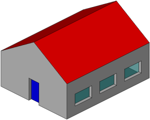
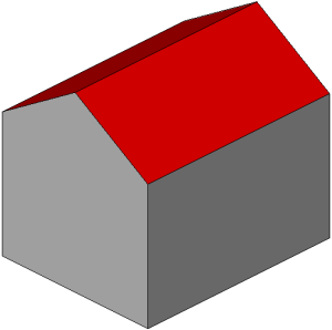
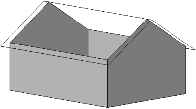
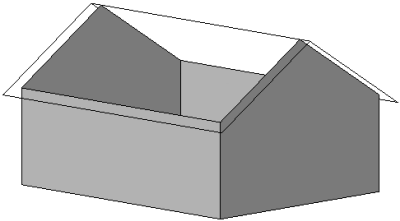
Examples
|
Detached family house |
|||||
|
|
|
|
|
|
|
|
Real Building |
CityGML LOD0 |
CityGML LOD1 |
CityGML LOD2 |
CityGML LOD3 |
|


Building Part (bldg:BuildingPart)
Definition
SIG3D: A building part is a sub-division of a building that is homogeneous related to its physical, functional or temporal aspects and may be considered as a building.
The subdivision of a building can be done by different criteria, e.g.
- structural like number of floors, roof type, height, construction method,
- administrative like building function, ownership, year of construction.
Building parts (bldg:BuildingParts) must satisfy the following conditions ( necessary conditions ):
- A building part always has a relation (bldg:consistsOfBuildingPart) to exactly one building:
- Buildings and building parts touch each other planar or linear-shaped,
- Building parts must be "connected to ground" and can have the following properties ( for example, storeys are no building parts ):
- Building parts may have different building attributes ( e.g. function, roof type ),
- Building parts may have an address that differs from the address of the building,
- The geometry of building parts (bldg:BuildingParts) must be modeled in a way that both the volume and the surfaces of the boundary surfaces ( wall surfaces, roof surfaces and ground surfaces ) correspond to the real conditions (see chapter Building Part/Geometry),
- If a building part is emphasized as the main part of the building, its semantics and geometry can be modeled in the parent building,
- Building parts will not be subdivided into further building parts.
CityGML Feature
bldg:BuildingPart
Geometry
- gml:Solid
- see also Modeling Guide for 3D Objects - Part 1
- It is recommended to use gml:Solid depending on the LoD in the following way :
- In LoD1 a solid directly contains the bounding geometry (Figure A)
- In LoD2 and LoD3 a solid contains external references (Xlinks) to the bounding geometry (wall surfaces, roof surfaces, ground surfaces, outer ceiling surfaces, outer bottom surfaces and closure surfaces as well as doors and windows). Surfaces, which do not exist in reality are modeled as closure surfaces (Figure B).
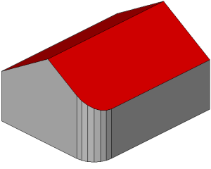
- In LoD2 a solid contains external references (Xlinks) to the real bounding geometry. Surfaces, which do not exist in reality are modeled as closure surfaces and assigned directly to the building part (Figure C).
|
|
|
|
|
|
|
|
|
Figure A |
Figure B |
Figure C |


- bldg:boundedBy (LoD2, LoD3)
- Relation to boundary surfaces (wall surfaces, roof surfaces, ground surfaces, outer ceiling surfaces, outer floor surfaces and closure surfaces)
gml:MultiSurface (not recommended)
gml:MultiCurve (not recommended)
Attributes
Since the building part is derived from the building, all attributes of the building are also available for the building part (see also Building Attribute).
Exception: bldg:consistsOfBuildingPart
Examples
|
Office with factory hall |
|
|
|
|
|
"structurally distinct" building parts → "Office" as function of BuildingPart 1 ; "Factory Hall" as function of BuildingPart 2 |

|
Detached house with staggered shed roof |
House with a projecting floor |
|
|
|
|
No "structurally distinct" building parts → roofType "staggered shed roof" |
No "structurally distinct" building parts; 1 building part not "connected to ground" |


Examples with overarching building parts
Variante 1

Variante 2

Variante 3

Building Installations (bldg:BuildingInstallation)
Definition
SIG3D: Permanently installed parts of the buildings outer shell which are accessory for the building structure including loggia, dormer, etc. Doors and windows are modeled by the corresponding CityGML classes.
CityGML Feature
- LOD1: not available
- LOD2: bldg:BuildingInstallation
- LOD3: bldg:BuildingInstallation
Geometry
- gml:Geometry
- gml:Geometry allows points, lines, areas, volumes as well as any combination of these elements.
- The use of points is not recommended.
- The use of lines is only recommenced under certain circumstances, because not all applications are able to process this geometry.
|
|
|
|
|
Lines (e.g. Antenna) |
Surfaces (e.g. Solar Panel) |
Volumes (e.g. Chimney) |


|
|
|
|
|
Lines and surfaces (e.g. satellite dish) |
Lines and surfaces resp. surfaces and volumes (e.g. stair and porch) |
Lines, surfaces und volumes (e.g. balcony) |


- bldg:boundedBy (LoD2, LoD3)
- Relation to boundary surfaces (wall surfaces, roof surfaces, ground surfaces, outer ceiling surfaces, outer floor surfaces and closure surfaces) → see also Extended Modeling
|
|
|
|
|
|
|
Building with a small ridge turret (modeled as a building installation with geometry) |
Building with a tower (modeled as a building installation with boundary surfaces) |


Attributes
- gml:id (mandatory)
- from GML version 3.2 onwards an id is mandatory
- bldg:class (LoD2, LoD3) (not recommended)
- The attribute bldg:class allows an unspecified classification of the building installation; no suggestion from the SIG3D;
- bldg:function (LoD2, LoD3) (recommended)
- The 'function' of a building installation is the predominantly functional significance of the building installation at the date of data collection ( principle of dominance ); see also in the SIG3D code lists.
- bldg:usage (LoD2, LoD3) (not recommended)
- no suggestion from the SIG3D;
- bldg:lodXGeometry (LoD2, LoD3)
- LoDX geometry of the building installation;
Examples
|
|
|
|
|
LoD1: no building installation |
LoD2: simplified building installation |
LoD3: detailed building installation |


|
|
|
|
|
LoD1: no building installation |
LoD2: simplified building installation |
LoD3: detailed building installation |


Ground Surfaces (bldg:GroundSurface)
Definition
SIG3D: Exterior, lower boundary surface of a building, building part or building installation against soil or water ( e.g. foundation ).
CityGML Feature
- LoD1: not available
- LoD2: bldg:GroundSurface
- LoD3: bldg:GroundSurface
Geometry
- gml:MultiSurface
- see also Modeling Guide for 3D Objects - Part 1
- A ground surface consists only of surfaces which are visible from the outside of the building, building part or building installation.

- The elevation of the ground surface depends on the availability of data:
- If there is information available about cellars, the elevation of the ground surface is set to the lower edge of the floor of the cellar (Figure A);
- If the ground surface of the building, building part or building installation is generated by an intersection with the terrain, the elevation of the (horizontal) ground surface is set to the lowest absolute height of the corresponding terrain intersection line (Figure B);
- It is not recommeded to generate the ground surface of the building, building part or building installation directly from an intersection with the terrain (Figure C);
|
|
|
|
|
Figure A |
Figure B |
Figure C |


Attribute
- bldg:lod2MultiSurface
- points to the LoD2 surface geometry of the base area
- bldg:lod3MultiSurface
- points to the LoD3 surface geometry of the base area
- bldg:opening not recommended
- points to a CityGML feature bldg:Opening ( bldg:Door ( see doors ) or bldg:Window ( see windows ) )
Examples
|
|
|
|
|
|
Building without cellar and one floor slab (One bldg:GroundSurface) |
Building with cellar and one floor slab (One bldg:GroundSurface) |
Building with partial cellar and two different floor slabs (Two bldg:GroundSurface) |
Building with cellar and ramp (Two bldg:GroundSurface) |


|
|
|
|
|
Building with ground surface at lower edge of floor cellar (One bldg:GroundSurface) |
Building with ground surface at lowest absolute height of the corresponding terrain intersection line (One bldg:GroundSurface) |
Building with ground surface based on intersection with the terrain (One bldg:GroundSurface) not recommended |


Wall Surfaces (bldg:WallSurface)
Definition
SIG3D: A wall surface is an exterior, lateral boundary surface of a building, building part or building installation.
ISO: A wall is a vertical construction that bounds or subdivides a space and usually fulfils a loadbearing or retaining function.
The normals of the wall surfaces should generally lie in the horizontal ( up to 45 degrees ).
CityGML Feature
- LoD1: not available
- LoD2: bldg:WallSurface
- LoD3: bldg:WallSurface
Geometry
- gml:MultiSurface
- see also Modeling Guide for 3D Objects - Part 1
- A wall surface surface consists only of surfaces which are visible from the outside of the building, building part or building installation.

- Wall projections, which do not limit the volume of the building will be modeled according to the rules for
Cantilevered building elements.
- A wall surface must consist of several surfaces ( SurfaceMember ) if :
- a wall surfaces has different colors or textures
4 wall surfaces with 3 areas each (1 area in "orange"; 2 areas in "beige")(4 bldg:WallSurface) 4 wall surfaces with 2 areas each (1 area with texture "plaster"; 1 area with texture "sandstone") (4 bldg:WallSurface) - a wall surface is nonplanar
5 wall surfaces; 4 wall surfaces with 1 surface each and 1 wall surface (circular wall) with 6 surfaces (4 bldg:WallSurface) Front wall as 1 wall surface consisting of 4 surfaces (revealing areas); right wall as 1 wall surface consisting of 13 surfaces (12 revealing areas)
- a wall surfaces has different colors or textures
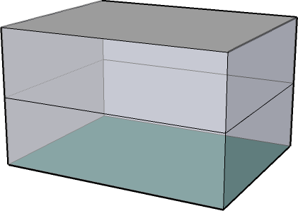
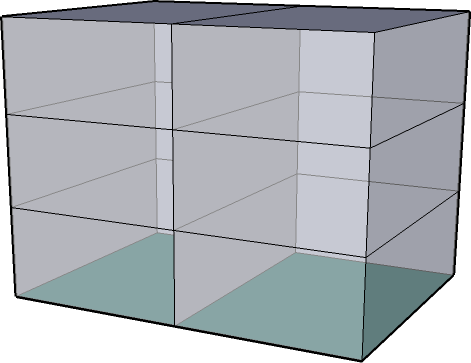
- A wall surface might consist of several surfaces ( SurfaceMember ) if :
- it is intended to indicate a storey structure

4 wall surfaces with 1 surface each (4 bldg:WallSurface) 4 wall surfaces with 3 surfaces each (ground floor, upper floor and top floor) (4 bldg:WallSurface)
- it is intended to indicate a storey structure


Attributes
- bldg:lod2MultiSurface
- points to the LoD2 surface geometry of the wall
- bldg:lod3MultiSurface
- points to the LoD3 surface geometry of the wall
- bldg:opening
- points to a CityGML feature bldg:Opening ( bldg:Door ( see doors ) or bldg:Window ( see windows ) )
Examples
|
|
|
|
|
A wall surface with 4 surfaces (1 bldg:WallSurface) not recommended |
4 wall surfaces with 1 surface each (4 bldg:WallSurface) |
4 wall surfaces (3 planar walls with 1 surface each and 1 circular wall with 12 surfaces) (4 bldg:WallSurface) |
|
|
|
|
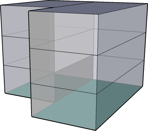
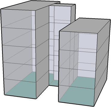
1 wall surface with elliptic or circular layout (1 bldg:WallSurface) |
5 wall surfaces by staggered facades (5 bldg:WallSurface) |


Roof Surfaces (bldg:RoofSurface)
Definition
SIG3D: A roof surface is a exterior, upper boundary surface of a building, building part or building installation, whose primary function is to protect from the effects of weather. ISO: A roof is a construction that encloses a building from above
The normals of a roof should generally lie in the vertical.
CityGML Feature
- LoD1: not available
- LoD2: bldg:RoofSurface
- LoD3: bldg:RoofSurface
Geometry
- gml:MultiSurface
- see also Modeling Guide for 3D Objects - Part 1
- A roof surface surface consists only of surfaces which are visible from the outside of the building, building part or building installation.

- Roof projections, which do not limit the volume of the building will be modeled according to the rules for cantilevered building elements.
Attributes
- bldg:lod2MultiSurface
- points to the LoD2 surface geometry of the roof
- bldg:lod3MultiSurface
- points to the LoD3 surface geometry of the roof
- bldg:opening
- points to a CityGML feature bldg:Opening ( bldg:Door ( see doors ) or bldg:Window ( see windows ) )
Examples
|
Gable Roof |
Gable Roof |
Mixed Roof |
Tent Roof |
|
|
|
|
|
|
1 roof surface with 2 surfaces (1 bldg:RoofSurface) not recommended |
2 roof surfaces with 1 surface each (2 bldg:RoofSurface) |
3 roof surfaces ( 2 planar roof surfaces with 1 surface each and 1 conical roof area with 12 surfaces ) (3 bldg:RoofSurface) |
1 conical roof area with 24 surfaces (1 bldg:RoofSurface) |


|
Jerkinhead Roof |
Gambrel Roof |
Arch Roof |
Dome Roof |
|
|
|
|
|
|
4 roof surfaces (4 bldg:RoofSurface) |
4 roof surfaces (4 bldg:RoofSurface) |
1 roof surface with 12 surfaces (1 bldg:RoofSurface) |
1 roof surface with 264 surfaces (1 bldg:RoofSurface) |


|
Shed Roof I |
Shed Roof II |
||
|
|
|
||
|
5 roof surfaces (5 bldg:RoofSurface) |
10 roof surfaces (10 bldg:RoofSurface) |


Outer Floor Surfaces(bldg:OuterFloorSurface)
Definition
SIG3D: Exterior, upper boundary surface of a building, building part or building installation which is not a roof.
The normals of an outer floor surface should generally be vertical directed upwards.
CityGML Feature
- LoD1: not available
- LoD2: bldg:OuterFloorSurface
- LoD3: bldg:OuterFloorSurface
Geometry
- gml:MultiSurface
- see also Modeling Guide for 3D Objects - Part 1
- An outer floor surface consists only of surfaces which are visible from the outside of the building, building part or building installation.
|
|
|


Attributes
- bldg:lod2MultiSurface
- points to the LoD2 surface geometry
- bldg:lod3MultiSurface
- points to the LoD3 surface geometry
- bldg:opening
- points to a CityGML feature bldg:Opening ( bldg:Door ( see doors ) or bldg:Window ( see windows ) )
Examples
|
Roof terrace |
Loggia |
Roof terrace |
|
|
|
|
|
1 OuterFloorSurface |
1 OuterFloorSurface |
1 OuterFloorSurface |


Outer Ceiling Surface(bldg:OuterCeilingSurface)
Definition
SIG3D: Exterior, lower boundary surface of a building, building part or building installation against air.
The normals of an outer ceiling surface should generally be vertical directed downwards.
CityGML Feature
- LoD1: not available
- LoD2: bldg:OuterCeilingSurface
- LoD3: bldg:OuterCeilingSurface
Geometry
- gml:MultiSurface
- see also Modeling Guide for 3D Objects - Part 1
- An outer ceiling surface consists only of surfaces which are visible from the outside of the building, building part or building installation.
|
|
|

Attributes
- bldg:lod2MultiSurface
- points to the LoD2 surface geometry
- bldg:lod3MultiSurface
- points to the LoD3 surface geometry
- bldg:opening
- points to a CityGML feature bldg:Opening ( bldg:Door ( see doors ) or bldg:Window ( see windows ) )
Examples
|
Passage |
Loggia |
Cantilevered floor |
|
|
|
|
|
1 OuterCeilingSurface |
1 OuterCeilingSurface |
1 OuterCeilingSurface |


Virtual Boundary Surface (bldg:ClosureSurface)
Definition
SIG3D: Exterior or interior boundary surface providing virtual boundaries, typically used to seal holes in volumetric objects.
CityGML Feature
- LoD1: not available
- LoD2: bldg:ClosureSurface
- LoD3: bldg:ClosureSurface
Geometry
- gml:MultiSurface
- see also Modeling Guide for 3D Objects - Part 1
- A closure surface consists only of virtual ( imaginary ) surfaces which are visible from the outside of the building, building part or building installation.
Attributes
- bldg:lod2MultiSurface
- points to the LoD2 surface geometry
- bldg:lod3MultiSurface
- points to the LoD3 surface geometry
- bldg:opening not recommended
- points to a CityGML feature bldg:Opening ( bldg:Door ( see doors ) or bldg:Window ( see windows ) )
Examples
|
Open barn |
Railway platform hall |
Parking garage |
|
|
|
|
|
1 ClosureSurface |
2 ClosureSurface |
28 ClosureSurface |


Doors (bldg:Door)
Definition
ISO 6707-1: Construction for closing an opening intended primarily for access or egress or both.
CityGML Feature
- LoD1: not available
- LoD2: not available
- LoD3: bldg:Door
Geometry
- gml:MultiSurface
- see also Modeling Guide for 3D Objects - Part 1
- A door consists only of surfaces which are either visible from the outside of the building, building part or building installation ( case A, B or C ) or consists of solids ( case D ).
|
|
|
|
|
|
|
|
|
|
|
Case A (Door as a simple surface) |
Case B (Door as a textured surface) |
Case C (Door modeled in detail with surfaces only visible from the outside) |
Case D (Door as a solid) |


- In order to ensure a closed outer shell of the building, the doors should not be modeled in an opened state ( case A ) but in closed condition ( case B ).
|
|
|
|
Case A (Doors opened) |
Case B (Doors closed) |


Attributes
- bldg:lod3MultiSurface
- points to the LoD3 surface geometry
- bldg:address
- points to the address of the door
Examples
|
Simple Doors |
Simple Doors with Embrasure |
Doors modeled in detail |
|
|
|
|
|
Number of Polygons (Complete Model) = 19 |
Number of Polygons (Complete Model) = 128 |
Number of Polygons (Complete Model) = 3498 |


Windows (bldg:Window)
Definition
SIG3D: Construction for closing an opening in a wall or roof, primarily intended to admit light and / or provide ventilation (cf. ISO 6707).
CityGML Feature
- LoD1: not available
- LoD2: not available
- LoD3: bldg:Window
Geometry
- gml:MultiSurface
- see also Modeling Guide for 3D Objects - Part 1
- A window consists only of surfaces which are either visible from the outside of the building, building part or building installation ( case A, B or C ) or consists of solids ( case D ).
|
|
|
|
|
|
|
|
|
|
|
Case A (Window as a simple surface) |
Case B (Window as a textured surface) |
Case C (Window modeled in detail with surfaces only visible from the outside) |
Case D (Window as a solid) |


- In order to ensure a closed outer shell of the building, the windows should not be modeled in an opened state ( case A ) but in closed condition ( case B ).
|
|
|
|
Case A (Windows opened) |
Case B (Windows closed) |


Attributes
- bldg:lod3MultiSurface
- points to the LoD3 surface geometry
Examples
|
Simple windows |
Simple windows with embrasure |
Windows modeled in detail |
|
|
|
|
|
Number of Polygons (Complete Model) = 28 |
Number of Polygons (Complete Model) = 412 |
Number of Polygons (Complete Model) = 6269 |


Extended Modeling
The Extended Modeling covers the modeling of frequently appearing architectural building components which significantly form the building's outer appearence. These building components are modeled as building installations as a general rule.
Balconies
Definition
SIG3D: A Balcony is a platform attached to a building which lies above the terrain level and projects from the building structure. It is supported by columns or console brackets, and enclosed with a balustrade [cit. en. Wikipedia]. The word's origin lies in the Italian word "balcone", which itself originates from the old-high-german word "balcho".
CityGML Feature
- LOD1: not available
- LOD2: bldg:BuildingInstallation
- LOD3: bldg:BuildingInstallation
Geometry
- gml:Geometry recommended
- Threshold LOD2:
- Modeling only, if the balcony's depth >= 0.5 m;
- Plane ground-area, if the component's thickness <= 0.5 m;
- Plane side-walls, if the component's thickness <= 0.5 m;
- Modeling only, if the balcony's depth >= 0.5 m;
- Threshold LOD3:
- Modeling only, if the balcony's depth >= 0.2 m;
- Plane ground-Area, if the component's thickness <= 0.2 m;
- Plane side-walls, if the component's thickness <= 0.2 m;
- Modeling only, if the balcony's depth >= 0.2 m;
- Modeling principle
- The building contains all geometry-containing border surfaces.
- The balcony is modeled as a Building Installation with Geometry. That is without semantic differentiation.
- The building's volume references (Xlink) to the corresponding boarder surfaces.
- Threshold LOD2:
|
|
| Modeling principle of a balcony |

- bldg:boundedBy not recommended
Attributes
- bldg:function
- Balcony (1000); see SIG 3D Codelistrecommendation for bldg:BuildingInstallation --> function
- bldg:boundedBy
- not recommended: A Balcony is considered as one building component which is semantically not subdivided any further.
Examples
|
Balconies |
|||||
|
Real Building |
CityGML LOD0 |
CityGML LOD1 |
CityGML LOD2 |
CityGML LOD3 |
|
|
|
|
|
|
|
|
|
Above terrain level, projected from the building structure --> Balcony |
|||||


|
|
|
|
|
|
|
|
Above terrain level, partly projected from the building structure, not bounded by 3 walls --> Balcony (no Loggia) |
|||||


Loggias
Definition
SIG3D: A Loggia is an enclosed on top exterior room within the building footprint, which is surrounded by 3 walls at full storey height. From an architectonical point of view, a Loggia (from the Italian) is a room within a building, which opens to the exterior area by means of archs or other constructional appliances. At ground floor level, Loggias create a passage between the interior area and the exterior area. At upper floor levels, Loggias are used as connection passages or as outdoor seating.
CityGML Feature
- LOD1: not available
- LOD2: bldg:BuildingInstallation
- LOD3: bldg:BuildingInstallation
Geometry
- gml:Geometry not recommended
- bldg:boundedBy recommended
- Threshold LOD2:
- Modeling only, if the Loggia's depth >= 0.5 m;
- Threshold LOD3:
- Modeling only, if the Loggia's depth >= 0.2 m;
- Modeling Principle
- The building contains all geometry-containing boundary surfaces
- Threshold LOD2:
- The Loggia (BuildingInstallation) references (Xlink) to the building's corresponding boundary surfaces. If the Loggia's floor is not part of the exterior building structure, it will be modeled as boundary surface at the building installation.
- The building's volume references (Xlink) to the building's corresponding boundary surfaces.
|
|
| Modeling Principle of a Loggia |

Attributes
- bldg:function
- Loggia (1001); see SIG 3D Codelist recommendation for bldg:BuildingInstallation --> function
- bldg:boundedBy
- recommended: A Loggia is considered as a building component which semantically consists of the building's boundary surfaces and possibly an exterior floor surface.
Examples
|
Loggien |
|||||
|
Real Building |
CityGML LOD0 |
CityGML LOD1 |
CityGML LOD2 |
CityGML LOD3 |
|
|
|
|
||||
|
|
|||||
|
|
|
||||
|
|
|
||||
|
|
|||||
|
|
|
||||
|
|
|||||
|
200px Loggias across half the front-width (row house) |
[[image:|200px]] Kamen Am Langen Kamp 25 |
||||
|
200px Projecting Loggias |
|
||||


* In this example, the geometry is modeled within the lod2Solid but not within the specified BoundarySurface elements (opposed to the standard)!
Passages
Definition
SIG3D: An open Passage is a part of a building at ground level for vehicles to drive through the building. It is bounded by walls and a roof.
CityGML Feature
- LoD1: not available
- LoD2: bldg:BuildingInstallation
- LoD3: bldg:BuildingInstallation
Geometry
- gml:Geometry not recommended
- bldg:boundedBy recommended
- Threshold LOD2 / LOD3:
- Modeling only, if the passage's depth and height >= 2 m;
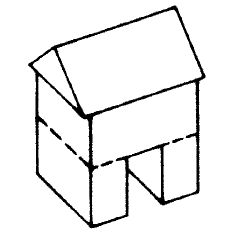
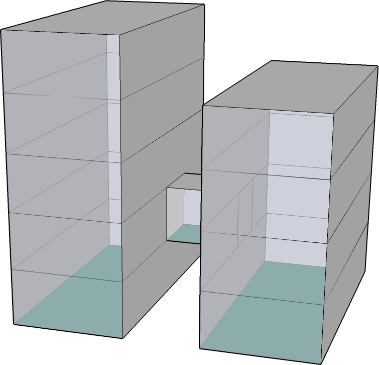
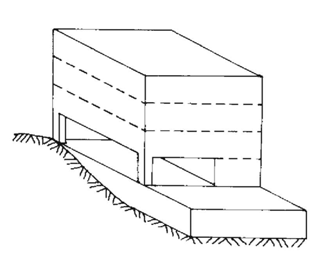
- Modeling Principle (passage in a building)
- The building contains all geometry-containing boundary surfaces.
- The passage (BuildingInstallation) references (Xlink) to the building's corresponding boundary surfaces.
- The building's volume references (Xlink) to the building's corresponding boarder surfaces.
Modeling principle of a passage
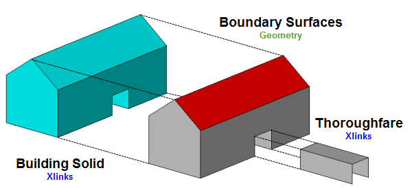
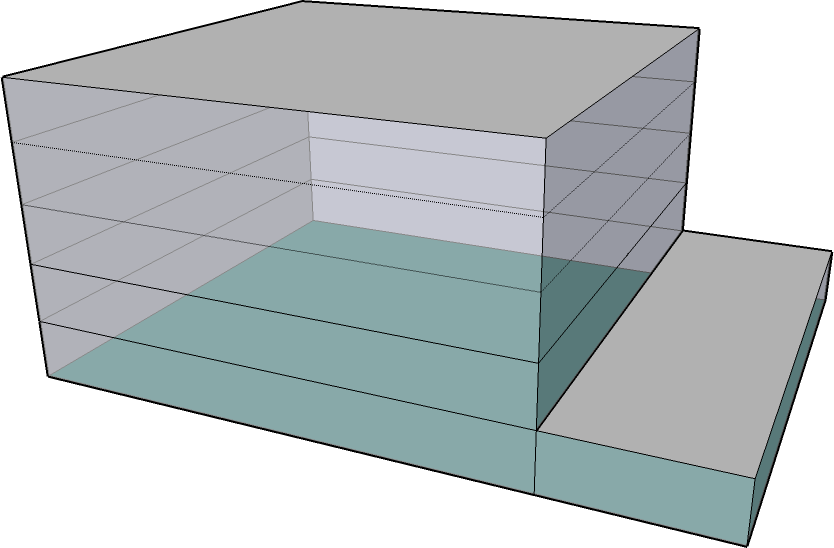
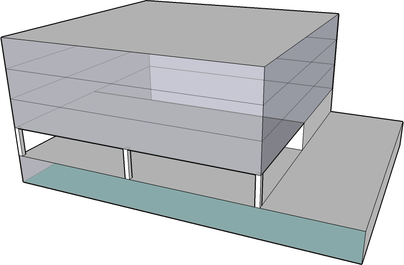
- Modeling Principle (Shared passage through two buildings)
- Each building contains all geometry-containing boundary surfaces
- The passage (BuildingInstallation) is assigned to the building which contains the greater part of the passage. The passage references (Xlink) to the building's corresponding boarder surfaces and complements the passage with bounding geometry at the BuildingInstallation.
- The building's volume references (Xlink) to the building's corresponding boarder surfaces.
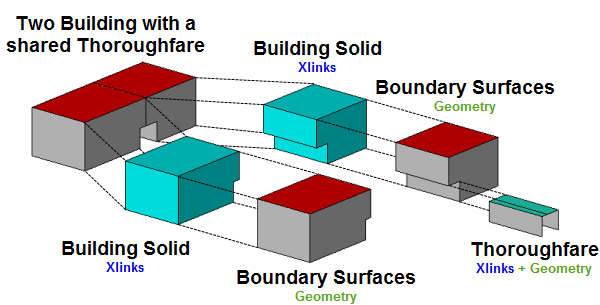
Modeling principle of a shared passage
Note: The modeling of buildings with a closed building construction is described in Kapitel 3.7Attributes
- bldg:function
- Passage(1002); see SIG 3D codelist recommendation for bldg:BuildingInstallation --> function
- bldg:boundedBy
- recommended: A passage is considered as a building component which semantically consists of the building's boundary surfaces and possibly an exterior floor surface.
Examples
Passages
Actual Example
CityGML LoD0
CityGML LoD1
CityGML LoD2
CityGML LoD3
 Passage inside of a building
200px Two buildings with a shared passage
Two buildings with separate passages
Two offset buildings with separate passages
200px Two buildings with onesided passage
200px Two buildings with a connection section
 Upper floor passage
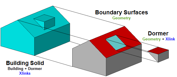
Dormers / Zwerchhaus (Zwerchgiebel)
Definition
SIG3D: SIG3D: A dormer' is a structural element of a building that protrudes from the plane of a sloping roof surface. Dormers are used, either in original construction or as later additions, to create usable space in the roof of a building by adding headroom and usually also by enabling addition of windows [Wikipedia].
A dormer does not lie on the same plane as the building's exterior wall. The dormer (or the dormer's footprint) has a minimum offset of 0,5 m and lies inside the building's footprint.
SIG3D: The Zwerchhaus is a one or more story installation of a sloping roof surface. It consists of a gable and its own roof. The !!!Zwerchgiebel!!! follows the exterior wall's building line. That represents the difference between a !!!Zwerchhaus!!! and a gable, because a gable does not have to follow the building line. The roof of the !!!Zwerchhaus!!! is often designed as a ridge roof. The ridge follows cross to the main roof's ridge. So the rainwater pipes continue in an orthogonal way to each other.
Note: The zwerchhaus is not modeled as a part of the building installation, but as a building's boundary surface itself.
CityGML Feature
- LOD1: not available
- LOD2: bldg:BuildingInstallation
- LOD3: bldg:BuildingInstallation
Geometry
- gml:Geometry not recommended
- bldg:boundedBy recommended
- Threshold LOD2:
- Modeling only, if the dormer's height >= 2 m;
- Threshold LOD3:
- Modeling Principle
- The building contains all geometry-containing boundary surfaces of the building structure. To close the building's volume, a ClosureSurface is modeled into the roof's gap.
- The dormer (BuildingInstallation) contains all geometry-containing boundary surfaces of the dormer. To close the volume, either a ClosureSurface is modeled or it is closed by referencing to the building's corresponding ClosureSurface (Xlink to OrientableSurface).
- The building's volume, the building structure's volume and the volume of the dormer (CompositeSolid) reference (Xlink)to the corresponding boundary surfaces of the building structure and dormer.
- Threshold LOD2:
Modelling Principle of a dormer Attributes
- bldg:function
- Dormer (1003); see SIG 3D codelisten recommendation forbldg:BuildingInstallation --> function
- bldg:boundedBy
- recommended: A dormer is considered as a building component which semantically consists of the building's boundary surfaces.
Examples
Dormer
Actual Example
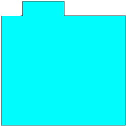
CityGML LOD0
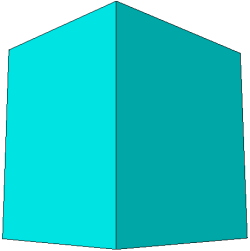
CityGML LOD1
CityGML LOD2
CityGML LOD3
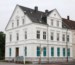
Dormer (Gable)
Real Building
CityGML LOD0
CityGML LOD1
CityGML LOD2
CityGML LOD3
Arcades / Architrav
Definition
SIG3D: An arcade is a succession of arches, each counter thrusting the next, supported by columns or piers, or a covered walk enclosed by a line of such arches on one or both sides. In warmer or wet climates, exterior arcades provide shelter for pedestrians.[Wikipedia]
SIG3D: An architrave (from Italian architrave, from Greek ἀρχι, archi- and Latin trabs, bar) is the lintel or beam that rests on the capitals of the columns. It is an architectural element in Classical architecture. In the ancient world, it was also called Epistyl because it was commonly built on pillars.[Wikipedia]
CityGML Feature
- LOD1: not available
- LOD2: bldg:BuildingInstallation
- LOD3: bldg:BuildingInstallation
Geometry
- gml:Geometry net recommended
- bldg:boundedBy recommended
- Threshold LOD2:
- Threshold-values for the modelling of beams: all sides of the beam's BoundingBox are >= 0.5 m
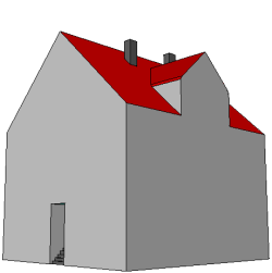
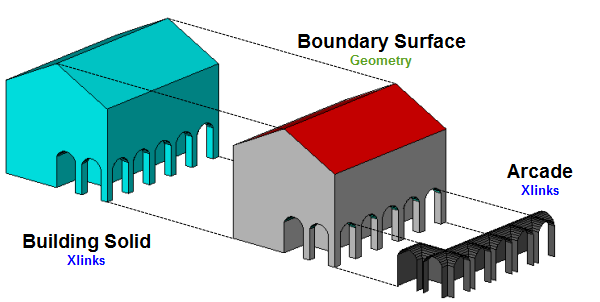
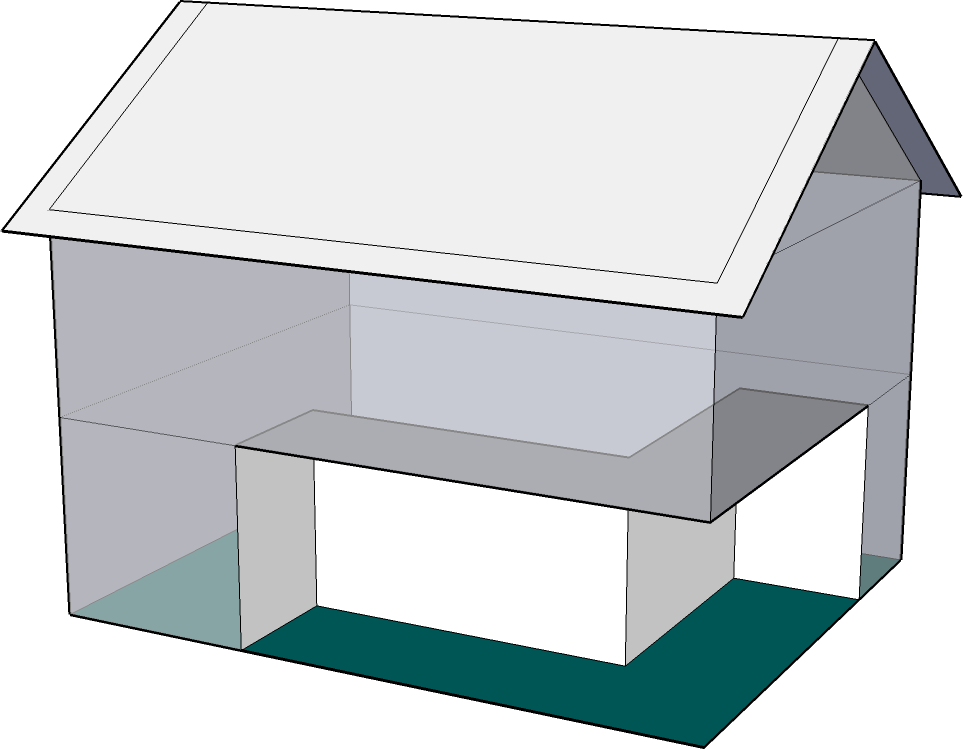
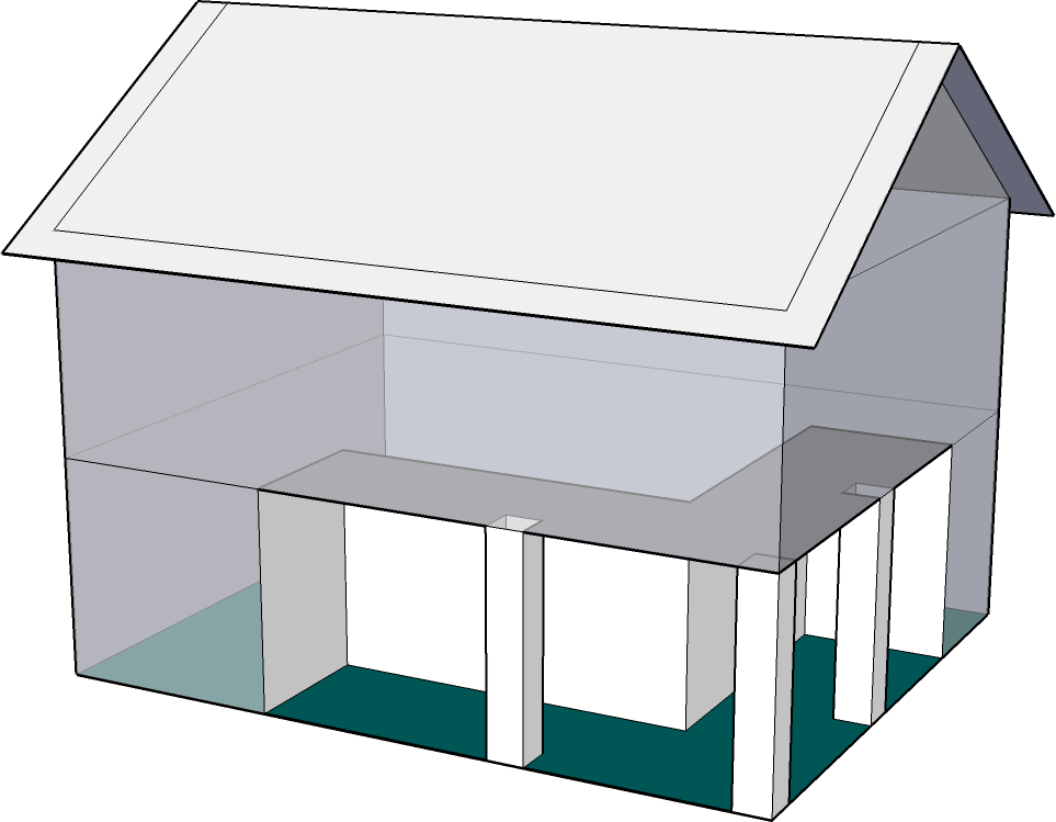
- Modelling principle
- The building contains all geometry-containing boundary surfaces
- The Arcade (BuildingInstallation) references (Xlink) to the building's corresponding boundary surfaces
- The building's volume references (Xlink) to the building's corresponding boundary surfaces
- Threshold LOD2:
Modelling principle of an arcade Attributes
- bldg:function
- Arcade (1009); see SIG 3D codelist recommendation for bldg:BuildingInstallation --> function
- bldg:boundedBy
- recommended: An Arcade is considered as a building component which semantically consists of the building's boundary surfaces.
Examples
Arcades
Actual example
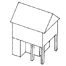
CityGML LOD0
CityGML LOD1
CityGML LOD2
CityGML LOD3

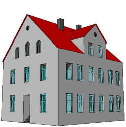
Arcade
Real Building
CityGML LOD0
CityGML LOD1
CityGML LOD2
CityGML LOD3
 This document is licensed under a Creative Commons Attribution-NonCommercial-ShareAlike 4.0 International License.
- Threshold LOD2 / LOD3:


