Difference between revisions of "Modeling Guide for 3D Objects - Part 1: Basics (Rules for Validating GML Geometries in CityGML)"
| Line 470: | Line 470: | ||
Due to the missing constraints it is recommended that MultiSurface elements should only be used to model non-volumetric parts of the building model as shown in Figure 8. Volumetric parts should be modeled as solids (see gml:Solid) | Due to the missing constraints it is recommended that MultiSurface elements should only be used to model non-volumetric parts of the building model as shown in Figure 8. Volumetric parts should be modeled as solids (see gml:Solid) | ||
| − | |||
| − | |||
| − | |||
| − | |||
| − | |||
| − | |||
| − | |||
| − | |||
<table width="900px" border="0" cellspacing="0"> | <table width="900px" border="0" cellspacing="0"> | ||
Revision as of 13:40, 11 November 2013
Document History
|
Version |
Date |
Author/s |
Status |
Remarks |
|---|---|---|---|---|
|
0.1.0 |
01.10.2010 |
Coors |
nicht öffentlich |
Erstfassung |
|
0.2.0 |
14.10.2010 |
Coors |
nicht öffentlich |
Solid ergänzt |
|
0.3.0 |
23.10.2010 |
Gröger |
nicht öffentlich |
Verschmelzung mit Paper Gröger |
|
0.4.0 |
23.11.2010 |
Coors |
nicht öffentlich |
Redaktionelle Änderungen und Ergänzungen zu Planarität von Polygonen |
|
0.5.0 |
24.11.2010 |
Gröger |
nicht öffentlich |
Einarbeitung der Änderungen, die im CityGML-Forum von K.-H. Häfele vorgeschlagen wurden |
|
0.6.0 |
15.12.2010 |
Gröger |
öffentlich |
Einarbeitung der Anregungen von G. Juen |
|
0.7.0 |
20.01.2012 |
Karl-Heinz Häfele |
nicht öffentlich |
Konvertierung in Html, Verschiebung des Kapitel Planarität von Polygonen, Neues Kapitel CompositeSolid |
|
0.7.0 EN |
November 2013 |
Egbert Casper, Karl-Heinz Häfele |
not public |
first English Version |
References
- Cox, S., Daisey, P., Lake, R., Portele, C., Whiteside, A. (2004): OpenGIS Geography Markup Language (GML) Implementation Specification. Version: 3.1.1, OGC 03-105r1,
- Herring J. (2001): The OpenGIS Abstract Specification, Topic 1: Feature Geometry (ISO 19107 Spatial Schema), Open Geospatial Consortium, OGC Document Number 01-101. OGC.
- Gröger, G., Kolbe, T., Czerwinski, A., and Nagel, C. (2008) (Eds.): OpenGIS City Geography Markup Language (CityGML) Encoding Standard, OGC reference number OGC 08-007r1 version 1.0.0, 2008
- Gröger, G., Plümer, L. (2011): How to Achieve Consistency for 3D City Models. Geoinformatica, 15(1):137-165, DOI: 10.1007/s10707-009-0091-6.
Preliminaries
- The rules refer to GML Version 3.1.
- The rules are based on the validity of the data with regard to the XML-Schema of GML 3.1.
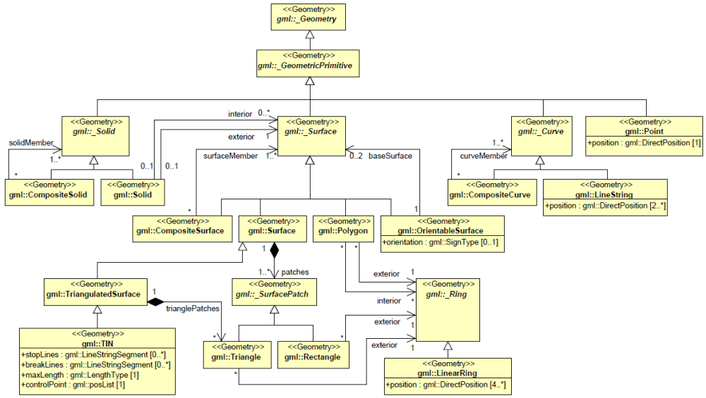
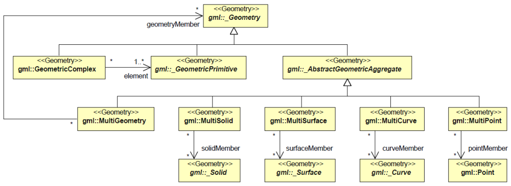
- The rules are restricted to the elements of GML that are used in CityGML (Profile of GML, c.f. Figure 1 and Figure 2).
- If a condition applies to CityGML only (not to GML in general), it is stated explicitly.
|
Figure 1: Profile of GML that is used in CityGML (Primitives and Composites) |
|
Figure 2: Profile of GML that is used in CityGML (Complexes and Aggregates) |
Spatial Reference Systems (SRS)
- Each geometry element (including pos, posList and coordinates) must
- either have a srsName attribute with proper value, or
- inherit the value of the srsName attribute from
- its parent geometries (even it its obtained recursively from the parents of the parents, etc.), or
- the gml:Envelope (or gml:Box) which is the value of the gml:boundedBy property of the parent feature or the parent feature collection (even if it is obtained recursively).
- A local value of a srsName attribute precedes the inherited value of a srsName attribute.
- If in geometries (pos, posList) the dimension of a SRS can not be derived from the SRS without a doubt, the attribute srsDimension must contain the dimension of the SRS.
Definitions
Geometric Tolerances
Planarity of Polygons
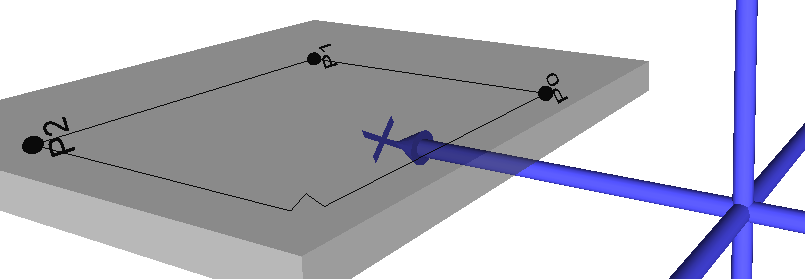
„Surfaces in CityGML are represented by polygons, which define a planar geometry, i.e. the boundary and all interior points are required to be located in one single plane.” (Gröger et al., 2008). The boundary of a Polygon is defined by one or more planar Linear Rings (see gml:Polygon). From practical point of view, Linear Rings that are not exactly planar should be accepted as a valid as well. Intuitively, a Linear Ring R would be defined as planar if there is a plane E with distance less than a given threshold for all points Pi of R. However, this is true for Linear Rings with small bends and folds as shown in Figure 3 as well.
|
Figure 3: : Bends and folds should not appear in planar Linear Rings |
|
In order to avoid such situations, a slightly different definition of planarity of Linear Rings is introduced:
Definition 1: A Linear Ring is planar, if it is a valid Linear Ring and the distance of all points to any plane , that is defined by three co-linear points , and , is less than a given threshold :
Für die Überprüfung der Planarität wäre es wünschenswert, eine Vorgabe für die Schranke zu haben.
Da die Eigenschaft der Planarität invariant gegenüber Skalierungen sein sollte,
sollte in den Wert von die Ausdehnung bzw. Größe (Flächeninhalt, max. Punktabstand) des Linearen Ringes eingehen.
Dazu sollte die Punktgenauigkeit bekannt/festgelegt sein.
gml:posList
- The number of items in the list should correlate with the product of the SRS dimension (usually in CityGML 3) and the number of positions.
gml:_Curve, gml:LineString
- Only gml:LineStrings are allowed as subtypes of _Curves (rule applies to CityGML only)
- A gml:LineString has linear interpolation.
- For the child elements of a gml:LineString (control points) the following statements must hold true:
- They form a sequence of "pos" (DirectPositionType) or "pointProperty" (PointPropertyType) elements. "pos" elements are control points that belong to this curve only. "pointProperty" elements contain points that may be referenced from other geometries or that reference other points (via XLinks) which are defined in other geometries.
- Alternatively, a gml:LineString can be composed of a "posList" element, providing a compact way of representing coordinates. In that case all control points must belong to the same Curve and must be given in the same SRS. The number of points (Direct Position) must be at least two.
- Each control point in a gml:LineString occurs only once, beside the first and the last one which may both be identical.
- Line segments of a gml:LineString are defined by pairs of two subsequent control points. Those line segments must not intersect mutually and must not have any identical points. Exceptions of that rule are the pairs which consist of an endpoint of one line segment and the start point of the next line segment in the sequence.
gml:LinearRing
The Linear Ring is the fundamental element to describe 3D geometry in CityGML. Every single polygon of a building geometry is defined by its boundary – the Linear Ring.
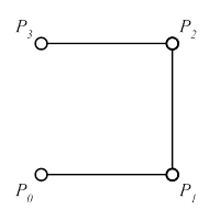
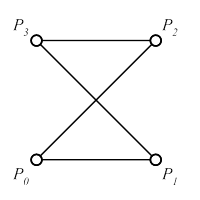
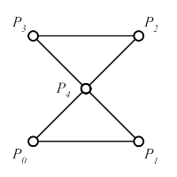
A sequence is an ordered list of elements. Unlike a set, order matters, and the exact same elements can appear multiple times at different positions in the sequence. A finite sequence with elements is denoted as . The empty sequence has no elements..
A finite sequence of points is a Linear Ring if:
(i) the first and last point and represent the same point: (closeness)
(ii) All points of the sequence besides start and end point are different:
(iii) Two edges and do only intersect in one start-/ endpoint. No other intersection is allowed (no self intersection).
If all points of the sequence are co-planar, the Linear Ring is planar.
Examples:
|
with
|
<gml:LinearRing> <gml:pos> 1 1 1 </gml:pos> <gml:pos> 3 1 1 </gml:pos> <gml:pos> 3 3 1 </gml:pos> <gml:pos> 1 3 1 </gml:pos> <gml:pos> 1 1 1 </gml:pos> </gml:LinearRing> |
|
|
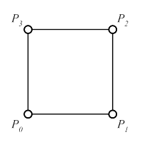
Figure 4: Planar Linear Ring: definition, GML and graphic representation |
||
Please note:
The two Linear Rings and are not identical.
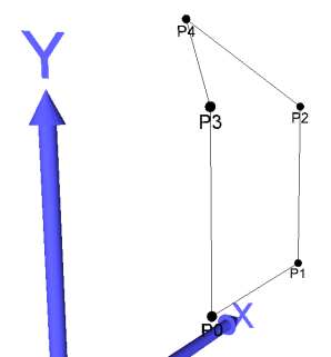 |
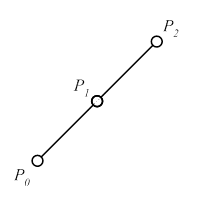 |
|
|
|
|
|
| Linear Ring, but not planar |
No Linear Ring: all 3 points are co-linear; self-intersection (see (iii)) |
|
| Figure 6: Special cases: non-planar and co-linear Linear Ring Elements. | ||
gml:Polygon
- Ein planarer linearer Ring definiert den Rand eines Polygons (äußerer Ring).
- Ein Polygon ist durch genau einen solchen äußeren Ring und innere Ringe definiert. Jeder innere lineare Ring muss ebenfalls planar sein, und der äußere und alle inneren linearen Ringe müssen in derselben Ebene (im Rahmen einer gegebenen Toleranz) liegen.
- Jeder innere lineare Ring muss innerhalb des Gebiets der Ebene liegen, das der äußere Ring begrenzt.
| Figure 7: Polygon mit korrektem inneren Ring (links) und nicht korrektem inneren Ring (rechts) |
- Die inneren linearen Ringe dürfen nicht verschachtelt sein, d.h. kein innerer Ring liegt in dem Gebiet der Ebene, das ein anderer innerer Ring definiert.
| Figure 8: Polygon mit zwei korrekten inneren Ringen (links) und zwei verschachtelten, nicht korrekten inneren Ringen (rechts) |
- Die inneren Ringe und der äußere Ring dürfen sich paarweise in endlich !!!!! (evtl. nur einer) vielen Punkten berühren. Dabei muss das Innere des Polygons zusammenhängend sein.
| Figure 9: Polygon mit korrektem, innerem Ring, der den außeren Ring an einem Punkt berührt (links) und nicht korrektem innerem Ring, der den äußeren Ring an zwei Punkten berührt und damit dass Polygon spaltet (rechts) |
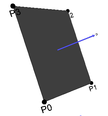
- Die Reihenfolge der Punkte des äußeren Linear Rings definiert die Orientierung des Polygons. In existieren mindestens drei nicht ko-lineare Punkte , und , die eine Ebene aufspannen. Der Vektor , der sich aus dem normalisieren Kreuzprodukt der beiden Vektoren und ergibt, wird als Flächennormale des Polygons bezeichnet:
Bemerkung: Aufgrund der Toleranz planarer linearer Ringe ist die Flächennormale des Polygons nicht eindeutig bestimmt.
Hinweis: Die beiden von den linearen Ringen und definierten Polygone haben dieselbe geometrische Ausprägung, unterscheiden sich aber hinsichtlich der Orientierung.
| Figure 10: Polygon mit Flächennormale n |
gml:OrientableSurface
- If the value of the attribute “orientation” of an OrientableSurface is "+", the orientation of the OrientableSurface is identical to the one of the baseSurface. If the value of “orientation is " ", the normal of the OrientableSurface has a direction which is opposite to the normal of the baseSurface. The default value of “orientation” is "+".
- Either the element “baseSurface” references the base surface via a XLink attribute or the element “baseSurface” contains the base surface as child element. The base surface has positive orientation.
gml:MultiSurface
A MultiSurface is an unstructured set of polygons. No further constraints are defined for a MultiSurface element. It is not necessary that M is a connected surface. Orientation of the polygons is arbitrary. By a MultiSurface any existing polygonal boundary representation of a rigid body can be described. Unfortunately, also objects that do not exist in real space can be modeled.
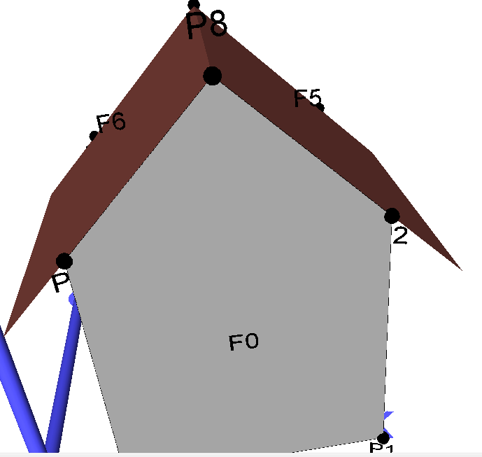
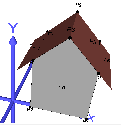
Due to the missing constraints it is recommended that MultiSurface elements should only be used to model non-volumetric parts of the building model as shown in Figure 8. Volumetric parts should be modeled as solids (see gml:Solid)
|
Figure 11: Modeling overlapping roof parts Please note: the left model in Figure 8 is created with a MultiSurface element containing 7 polygons. However, the polygons do not represent a valid boundary of a rigid body. Calculating a volume is not possible. The right model is the same building geometry but modeled with 1 Solid element (7 polygons) and 1 MultiSurface element (2 polygons F6 and F8) as recommended (see CityGML Standard v1.0,p.61) |
|
gml:CompositeSurface
Eine CompositeSurface ist eine Menge von Polygonen, für die folgendes gilt:
- Die Schnittmenge zweier Polygone und aus ist entweder leer oder besteht nur aus Punkten und/oder Kanten, die auch in den beiden linearen Ringen vorkommen. Bezeichne den planaren linearen Ring, der das Polygon definiert. Dann gilt:
- Jede Kante eines linearen Rings , der ein Polygon definiert, wird höchstens einmal als Kante in einem linearen Ring genutzt, der ein anderes Polygon definiert.
Es gilt und . - Die Polygone aus sind so orientiert, dass die Flächennormale benachbarte Polygone in dieselbe Richtung zeigen.
- Die Vereinigung aller Polygone aus ohne die Kanten oder Punkte, in denen sich die Polygone berühren, ist isomorph zu einem Polygon.
Aus (1) und (2) ergibt sich, dass die Oberfläche, die durch beschrieben wird, keine sich gegenseitig überlappenden oder durchdringenden Polygone enthalten darf (Polygone berühren sich höchstens in Punkten oder Kanten).
gml:Solid
Ein Solid modelliert einen beliebigen Festkörper. Die Oberfläche des Solid wird über eine Menge von Polygonen beschrieben, die bestimmte strukturgebende Eigenschaften erfüllen müssen. Die Menge von Polygonen beschreibt die Oberfläche eines Solid genau dann, wenn gilt:
- Die Schnittmenge zweier Polygone und aus ist entweder leer oder besteht nur aus Punkten und Kanten, die auch in den beiden linearen Ringen vorkommen. Bezeichne den planaren linearen Ring, der das Polygon definiert. Dann gilt:
- Jede Kante eines linearen Rings , der ein Polygon definiert, wird genau einmal als Kante in einem linearen Ring genutzt, der ein anderes Polygon definiert.
Es gilt und . - Die Polygone aus sind so orientiert, dass die Flächennormalen nicht ins Innere des Festkörpers zeigen, sondern nach außen.
- Die Polygone aus sind zusammenhängend, d.h. in dem dualen Graphen von gibt es einen Weg, der alle Knoten umfasst. Der duale Graph GC =(VC, EC) von besteht aus einer Menge VC von Knoten und einer Menge EC von Kanten. Jeder Knoten v aus VC repräsentiert genau ein Polygon aus . Eine Kante zweier Polygone und aus wird in GC durch eine Kante in EC dargestellt.
- Für jeden Punkt , der in einem linearen Ring eines Polygons aus vorkommt, gilt: Der Graph , der aus Polygonen und Kanten gebildet wird, die berühren, ist zusammenhängend. Dabei repräsentiert jeder Knoten aus genau ein Polygon, dessen linearer Ring enthält. Zwei Knoten sind genau dann mit einer Kante aus verbunden, wenn die Polygone, die durch die Knoten repräsentiert werden, eine gemeinsame Kante haben, die berührt .
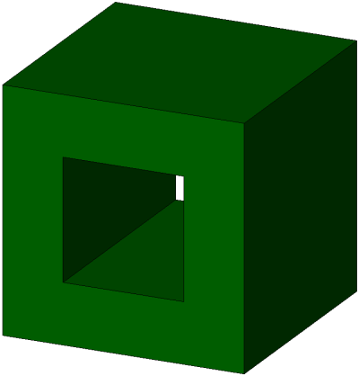
Aus (1) und (2) ergibt sich, dass die Oberfläche, die durch beschrieben wird, keine Löcher enthalten darf. Mit den weiteren Bedingungen (4) und (5) ergibt sich, dass das Innere des durch beschriebenen Festkörpers zusammenhängend sein muss. wird auch als geschlossene CompositeSurface bezeichnet.
Beispiele:
|
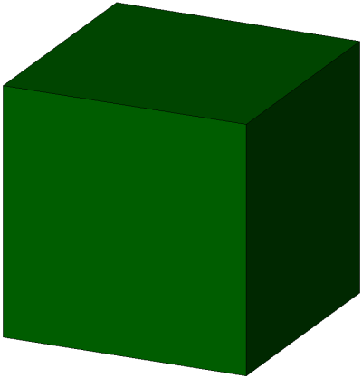
Korrekt: 6 Flächen, geschlossen, Flächenorientierung korrekt |
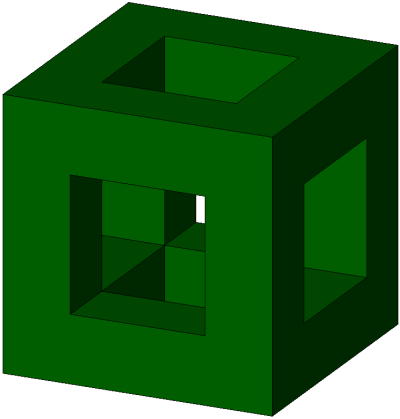
Korrekt: 11 Flächen, geschlossen, Flächenorientierung korrekt |
Korrekt: 10 Flächen, geschlossen, Flächenorientierung korrekt |
Korrekt: 30 Flächen, geschlossen, Flächenorientierung korrekt |
|
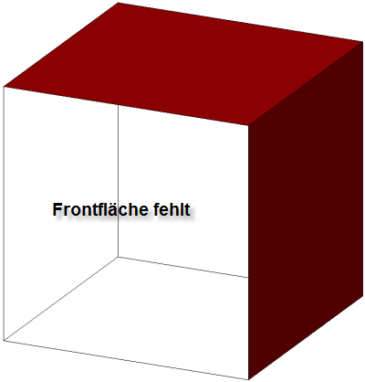
Nicht Korrekt: 5 Flächen, nicht geschlossen, Flächenorientierung korrekt |
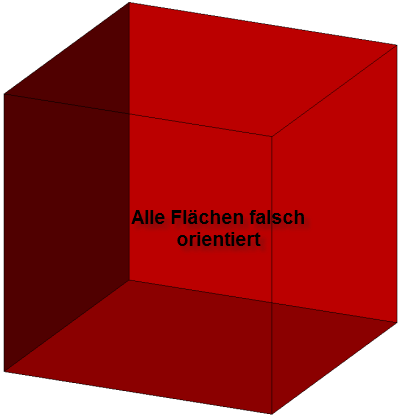
Nicht Korrekt: 6 Flächen, geschlossen, Flächenorientierung nicht korrekt |
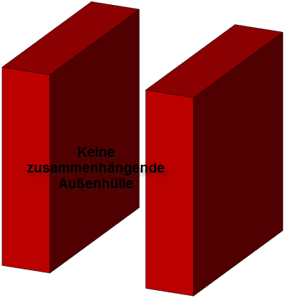
Nicht Korrekt: 12 Flächen, nicht geschlossen (zwei Außenhüllen), Flächenorientierung korrekt |
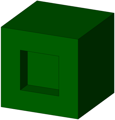
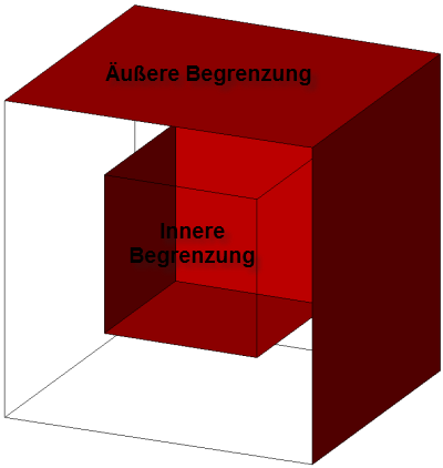
Nicht Korrekt: 12 Flächen, nicht geschlossen (innere und äußere Hülle), Flächenorientierung korrekt |
gml:CompositeSolid
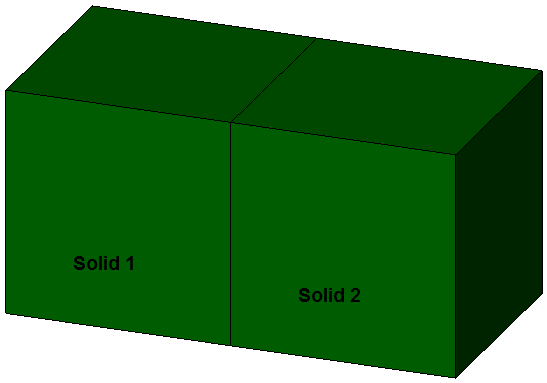
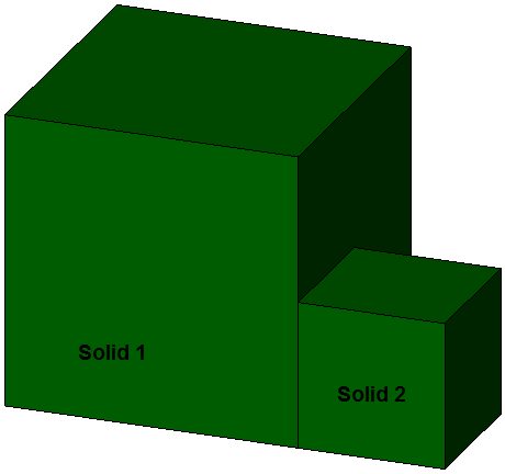
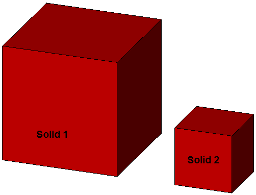
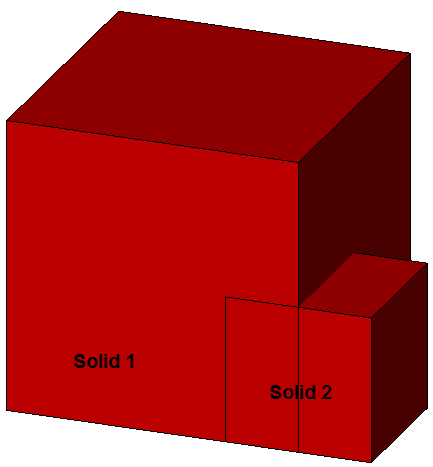
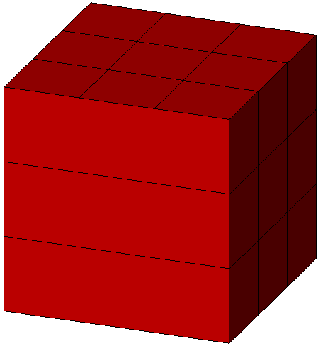
Ein CompositeSolid wird durch eine nichtleere Menge von Solids (vgl. 12.) beschrieben, für die gilt:
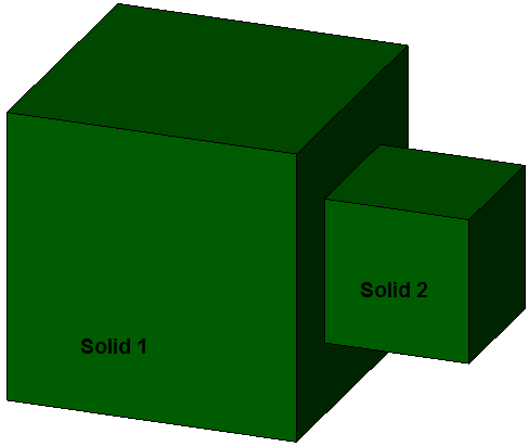
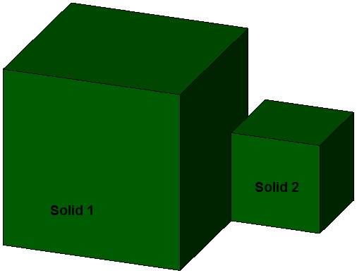
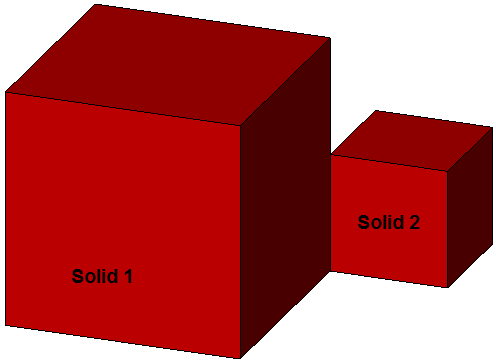
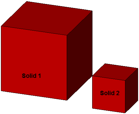
- Der Schnitt der Inneren zweier Solids , , 1 ≤ i ≤ n, 1 ≤ j ≤ n, i ≠ j, ist leer, d.h. entweder sind beide Solids , disjunkt oder beide berühren sich nur in Flächen, Linien oder Punkten
- Sei die Vereinigung aller Solids aus . Dann ist die Begrenzung von (die Oberfläche von ohne die Flächen oder Punkte, in denen sich die Solids berühren) die Begrenzung eines Solid.
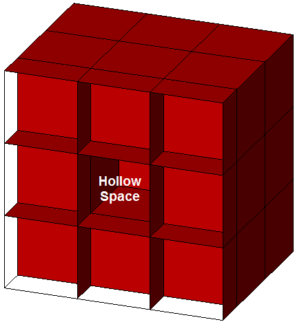
In CityGML werden bei CompositeSolids ebenso wie bei Solids innere Einschlüsse (Hohlräume) nicht betrachtet.
Examples:
|
Korrekt; Flächenberührung |
Korrekt; Flächenberührung |
Korrekt; Flächenberührung |
Korrekt; Flächenberührung |
|
Falsch; Linienberührung |
Falsch; Punktberührung |
Falsch; keine Berührung |
Falsch; Durchdringung |
|
Falsch; 26 Quader mit Flächenberührung |
aber mit Hohlraum |
nicht korrekt; Innere Begrenzung |
gml:Triangle
- A Triangle is a special case of a polygon that is bounded by one outer Linear Ring with four points.
- There are no interior rings (no element "interior").
gml:TriangulatedSurface
A triangulated surface is a CompositeSurface that consists of triangles only, but is not closed (it may have boundaries). There is no restriction on how the triangulation is derived.
gml:Tin
In contrast to a gml:TriangulatedSurface, the triangles of a gml:TIN are not represented explicitly, but by its three vertices (called control points). In addition, breaklines, stop lines and the maximal length of a side of a triangle can be represented in a gml:TIN.
- A TIN is a triangulated surface that is the result of the application of a Delaunay Algorithm or of a similar algorithm (extended by breaklines, stop lines and the maximal length of a side of a triangle). The surface satisfies the Delaunay criterion:
- For each triangle in the network, the circle passing through its vertices does not contain, in its interior, the vertex of any other triangle.
- Stoplines are lines where the local continuity or regularity of the surface is questionable. In the area of these pathologies, triangles intersecting a stopline shall be removed from the TIN surface, leaving holes in the surface. If triangles incident to the boundary of the surfaces are removed, the boundary of the surfaces changes.
- Breaklines are lines that are critical for the shape of the surface, representing local ridges, or depressions (such as drainage lines) in the surface. As such their constituent segments must be included in the TIN even if doing so violates the Delaunay criterion.
- Areas of the surface where the data is not sufficiently dense to assure reasonable calculations shall be removed by adding a retention criterion for triangles based on the length of their sides. For any triangle sides exceeding maximum length, the adjacent triangles to that triangle side shall be removed from the surface. # The number of control points is at least three.
- The surface is not affected by the order in which the control points are given. Application schemas may add information based on the ordering of the control points to facilitate the reconstruction of the TIN from the control points.
